
A Jetson Orin Nano can run object detection, speech recognition, and a ROS 2 navigation stack. With the right pins exposed on its carrier, it can also send PWM signals to a motor driver. If you already have a Jetson on your robot, what do you gain by adding a microcontroller?
High-level computing. Picture a rover approaching a chair. The Jetson processes the camera frames, plans a path around the chair, and sends the drive a target speed and turn rate.
Low-level control. The drive has to make the wheels follow that command. If one wheel rolls from tile onto carpet and slows down, a microcontroller reads the change at the encoder and adjusts the motor output. That correction can happen between camera frames.
The split also matters when something fails. If Linux reboots while the rover is moving at 0.2 m/s, a motor driver can hold its last input. A local controller can detect that commands have stopped and apply the drive’s configured stop. If your smart drive already handles wheel feedback, limits, and command timeouts, it may do that job without an extra board.
We measured how late a Linux thread woke under load on a Jetson Orin Nano in a Turing Pi 2.5. We also tested a command timeout on a PC for the other case, where the next command never arrives.
The short answer
| Job | Usual home | Note |
| Camera ingest, detection, tracking | Jetson | Needs the GPU and Linux software |
| Mapping, planning, navigation | Jetson | |
| Speech, user interface, logging | Jetson | |
| Choosing the next command | Jetson | |
| PWM waveform generation | Either | Jetson has hardware PWM controllers too; usable pins depend on your carrier |
| Encoder counting and wheel speed | Controller | Hardware counters do not depend on the scheduler |
| Closing the velocity loop | Controller, usually | Fine on a Jetson only if you measure the timing and accept the failure behavior |
| Command timeout, fault state, enable and disable | Controller or smart drive | Must survive a Linux failure |
| Velocity and acceleration limits at the actuator | Controller or smart drive | The last check before the driver |
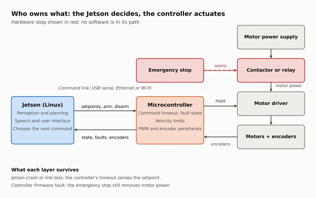
The command that crosses the link can be as simple as “drive forward at 0.2 m/s.” The wheel controller compares that target with the speed measured by the encoders and adjusts the motor driver. Encoder counts and fault reports travel back to the Jetson.
Why this is about timing and failure behavior, not power
A wheel-speed loop has several jobs to finish on each update. It reads the encoders, calculates a correction, and writes a new output to the motor driver. If Linux schedules the thread late, all three happen late. The PWM waveform can remain perfectly steady while the motor runs at the wrong speed.
Our Jetson ran JetPack 7.2.1 with full kernel preemption enabled (CONFIG_PREEMPT=y). You can check your build with zcat /proc/config.gz | grep PREEMPT. NVIDIA also offers a separate PREEMPT_RT kernel for Orin Nano, at developer-preview quality in Jetson Linux R39.2. It can reduce the delay before a high-priority thread runs. A command timeout running on the Jetson still stops working if the Jetson loses power. Jetson real-time kernel
What the Jetson can already do in hardware
- PWM waveform generation. PWM drives a motor by switching power on and off at a fixed frequency and varying the on-time. The Jetson is not limited to software-timed PWM: Jetson Linux documents hardware PWM controllers on Orin Nano (six are available to the kernel, enabled through the device tree). Whether a usable output pin exists depends on your carrier and pin configuration. Waveform generation alone is not a reason to add a controller.
- Feedback and command updates. Encoders report wheel rotation as pulses, and two offset channels (quadrature) give direction as well as distance. Counting pulses, computing wheel speed, and updating setpoints on a fixed schedule is where scheduling latency on a loaded Linux system can bite.
- Independent fault handling. Zeroing the outputs when commands stop, or when the Linux side crashes or reboots, is where a separate controller earns its place even if the Jetson’s PWM is perfectly stable.
What a microcontroller adds
A microcontroller moves the per-edge work into dedicated peripherals.
- The ESP-IDF pulse counter (PCNT) counts edges in a hardware unit. With a level signal as the direction input it decodes quadrature encoders, and each unit has a glitch filter that ignores short noise pulses.
- The motor control PWM (MCPWM) peripheral generates timed PWM with dead time between complementary outputs, accepts fault inputs from GPIO, and can brake either cycle by cycle or latched until software clears the fault.
On the original ESP32, hardware counts encoder edges and generates PWM pulses. Firmware still has to read the count, calculate wheel speed, and choose the next duty cycle. Check the peripherals on the exact chip you plan to use. The ESP32-C3, for example, lacks the MCPWM unit. ESP32 chip comparison
Two different timers matter on the ROS 2 side. The ros2_control controller manager defaults to 100 Hz, giving it 10 ms per update. Separately, diff_drive_controller treats a velocity command as stale after 0.5 s by default. That timeout helps if the publisher crashes while the controller manager is still running. A timeout on the wheel controller also covers a crash of the Jetson itself. Controller manager · Differential-drive controller
What breaks when one board does everything
| Event | One board does everything | Split design |
| Camera or AI pipeline spikes CPU and memory use | Software-timed loops share the machine, so their timing can slip | Encoder counting and PWM run in MCU peripherals and are unaffected |
| A Python or ROS node crashes | The process that held the motor command stops publishing, and the output can keep its last commanded state | The MCU’s command timeout trips and the setpoint goes to zero |
| The Jetson reboots or hangs | Pin states during boot depend on your carrier, pin configuration, and boot sequence, and you must verify them | The MCU holds its own safe state and boots on its own schedule |
| The link drops (cable fault, Wi-Fi loss) | The remote side keeps acting on the last command | The timeout trips and the setpoint goes to zero |
| A high-level bug commands full speed | The command reaches the motor driver directly | The MCU clamps velocity to local limits |
Where Turing Pi 2.5 fits
A network camera can stream video to the Jetson over Ethernet. If your camera uses a CSI ribbon cable, choose a carrier with a compatible camera connector. NVIDIA’s Orin Nano developer kit has two CSI connectors, four USB 3.2 Type-A ports, and a 40-pin expansion header. Developer kit connectors
On the Turing Pi 2.5, the slot determines which peripherals you can plug into the Jetson. Node 1 has the 40-pin GPIO header and a dedicated USB-A port. Node 4 has four USB 3.0 connections. Nodes 1 and 2 also expose USB through Mini PCIe for compatible modules. The board has two Gigabit Ethernet ports and an onboard switch. Slot and port mapping · Revision 2.5 USB changes
On the bench, power the board through its 24-pin ATX socket and connect the wheel controller over USB or the LAN. With the motor disconnected, pull the command cable and inspect the driver output. This checks whether the timeout actually changes the signal reaching the driver. Power connections
On a rover, the camera and wheel controller can ride on the chassis while the Jetson stays on the bench. If Wi-Fi drops, the Jetson loses the video feed and the rover stops receiving new commands. The onboard controller must be able to stop the drive on its own.
At a fixed inspection station, the Jetson can classify each part while a local controller triggers the reject gate. A jammed gate or moving conveyor still needs a way to stop independently of the vision software.
Linking them: ROS 2, micro-ROS, or a plain serial protocol
On the Jetson side, ROS 2 gives you a distributed publish and subscribe system. Its quality of service settings matter at this boundary: by default publishers and subscriptions use reliable delivery, and a subscription that requests reliable delivery will not connect to a best-effort publisher.
| micro-ROS | Plain serial protocol | |
| What you get | The MCU appears as a ROS 2 node with topics you can inspect with standard tools | A small fixed set of messages you fully control |
| What it costs | An agent process on the Jetson, a build toolchain, and RAM on the MCU | You write and maintain the framing and parser |
| Choose it when | You want ROS 2 tooling end to end | You want the smallest auditable surface for the command and timeout logic |
With micro-ROS, an agent on the Jetson connects the MCU to the ROS 2 graph. The ESP-IDF component uses UDP by default and also supports serial. Its tested targets include ESP32, S2, S3, and C3. Budget RAM for the messages and entities your application uses. The client can allocate memory during setup and run without further allocations during normal message exchange. The ESP-IDF component is not production-ready. ESP-IDF component · Memory profile
Put the command timer on the MCU with either transport. If the agent exits or the serial cable comes loose, the MCU can still detect how long it has been since the last valid command.
What a good link contains
- Power-up disarmed, deliberate arming. The controller starts with outputs at zero and ignores motion commands until it receives an arm message that follows a human decision, not a script starting by itself.
- Command timeout on the controller. Every valid command resets a timer. On expiry the setpoint goes to zero and the controller faults. The check must run before a late command is accepted, and the control loop must call it often enough to keep the detection delay inside your budget.
- Deliberate re-arm. A fault clears only on a new arm message, and arming starts at zero velocity.
- Integrity and freshness. Frames carry a version and a CRC, which detects many transmission errors. Sequence numbers help reject duplicate or out-of-order frames. A delayed frame can still arrive in sequence, so define how the receiver decides whether a command is recent enough to use, and keep buffers shallow.
- Telemetry and limits. The controller reports state, faults, encoder counts, and command age, and it clamps speed (and, in a real robot, acceleration) whatever it is asked for.
A command-timeout state-machine example
This example implements part of that list: power-up disarmed, a timeout checked before commands are accepted, a latched fault with explicit re-arm, payload-length checks on arm and command messages, and velocity clamping. It does not implement the byte-level parser (which must check the version and CRC before handing a frame to the state machine), telemetry, sequence numbers, a freshness rule, acceleration limits, or any hardware integration. Treat it as the core of a command link, not the whole link.
| Field | Size | Notes |
| Start byte | 1 | 0xA5, lets the parser resynchronize after noise |
| Version | 1 | Currently 1; reject unknown versions |
| Type | 1 | 0x01 command, 0x03 arm, 0x04 disarm |
| Length | 1 | Payload bytes |
| Payload | N | Command: int16 linear velocity (mm/s) and int16 angular velocity (mrad/s), little-endian |
| CRC | 2 | CRC-16/CCITT-FALSE over version through payload, little-endian |
The host side builds frames in a few lines of Python:
import struct

SOF, VERSION = 0xA5, 1
MSG_CMD, MSG_ARM, MSG_DISARM = 0x01, 0x03, 0x04


def crc16_ccitt(data: bytes, crc: int = 0xFFFF) -> int:
    for b in data:
        crc ^= b << 8
        for _ in range(8):
            crc = ((crc << 1) ^ 0x1021) & 0xFFFF if crc & 0x8000 else (crc << 1) & 0xFFFF
    return crc


def build_frame(msg_type: int, payload: bytes = b"") -> bytes:
    body = struct.pack("<BBB", VERSION, msg_type, len(payload)) + payload
    return bytes([SOF]) + body + struct.pack("<H", crc16_ccitt(body))


def cmd_vel(lin_mm_s: int, ang_mrad_s: int) -> bytes:
    return build_frame(MSG_CMD, struct.pack("<hh", lin_mm_s, ang_mrad_s))
Sending is a loop over a serial port, started by a person:
import time
import serial  # pip install pyserial

port = serial.Serial("/dev/ttyUSB0", 115200)  # use your controller's device path
input("Wheels lifted and area clear? Press Enter to arm: ")  # a deliberate human step
port.write(build_frame(MSG_ARM))
while True:
    port.write(cmd_vel(200, 0))  # 0.2 m/s forward, no turn
    time.sleep(0.05)             # about 20 Hz
The controller side is a small state machine with no hardware dependencies, which is why it can be tested on a PC. Your parser checks the version and CRC and then feeds the frame to the state machine, which itself checks the arm and command payload lengths and clamps velocity. Firmware calls link_tick from the control loop and applies the velocities only while link_motion_allowed returns true. When it returns false, actively apply your driver’s configured stop or disable behavior: skipping the output write can leave the previous PWM duty cycle active. The limits shown are placeholders: set them from your robot.
#include <stdint.h>
#include <stdbool.h>

#define LINK_TIMEOUT_MS      200u   /* tune to your robot's stopping distance */
#define LINK_MAX_LIN_MM_S    500    /* example limits: set them from your robot */
#define LINK_MAX_ANG_MRAD_S  1000

enum { MSG_CMD = 0x01, MSG_ARM = 0x03, MSG_DISARM = 0x04 };
typedef enum { LINK_DISARMED, LINK_ARMED, LINK_FAULT } link_state_t;

typedef struct {
    link_state_t state;
    uint32_t last_rx_ms;
    int16_t  lin_mm_s;     /* velocity setpoint to apply, already clamped */
    int16_t  ang_mrad_s;
} link_t;

static void link_stop(link_t *l) { l->lin_mm_s = 0; l->ang_mrad_s = 0; }

static int16_t clamp16(int16_t v, int16_t lim) {
    return v > lim ? lim : (v < -lim ? (int16_t)-lim : v);
}

void link_init(link_t *l) {
    l->state = LINK_DISARMED;
    l->last_rx_ms = 0;
    link_stop(l);
}

/* Call from the control loop on every cycle. The longest gap between calls
   adds to the worst-case time to notice a lost link (timeout + tick gap).
   Unsigned subtraction survives the millisecond counter wrapping around. */
void link_tick(link_t *l, uint32_t now_ms) {
    if (l->state == LINK_ARMED &&
        (uint32_t)(now_ms - l->last_rx_ms) > LINK_TIMEOUT_MS) {
        link_stop(l);
        l->state = LINK_FAULT;      /* stays here until an explicit ARM */
    }
}

/* Call for every frame that has already passed the version and CRC checks. */
void link_on_frame(link_t *l, uint8_t type, const uint8_t *p, uint8_t len,
                   uint32_t now_ms) {
    link_tick(l, now_ms);           /* expire first: a late command must not
                                       revive a session that already timed out */
    switch (type) {
    case MSG_ARM:
        if (len == 0) {
            link_stop(l);
            l->state = LINK_ARMED;
            l->last_rx_ms = now_ms;
        }
        break;
    case MSG_DISARM:                /* always honored: stopping is the safe direction */
        link_stop(l);
        l->state = LINK_DISARMED;
        break;
    case MSG_CMD:
        if (l->state == LINK_ARMED && len == 4) {
            int16_t lin = (int16_t)((uint16_t)p[0] | ((uint16_t)p[1] << 8));
            int16_t ang = (int16_t)((uint16_t)p[2] | ((uint16_t)p[3] << 8));
            l->lin_mm_s   = clamp16(lin, LINK_MAX_LIN_MM_S);
            l->ang_mrad_s = clamp16(ang, LINK_MAX_ANG_MRAD_S);
            l->last_rx_ms = now_ms;
        }
        break;
    }
}

/* When this returns false, actively apply your driver's stop or disable
   behavior. Skipping the next output write can leave the old PWM duty active. */
bool link_motion_allowed(const link_t *l) { return l->state == LINK_ARMED; }
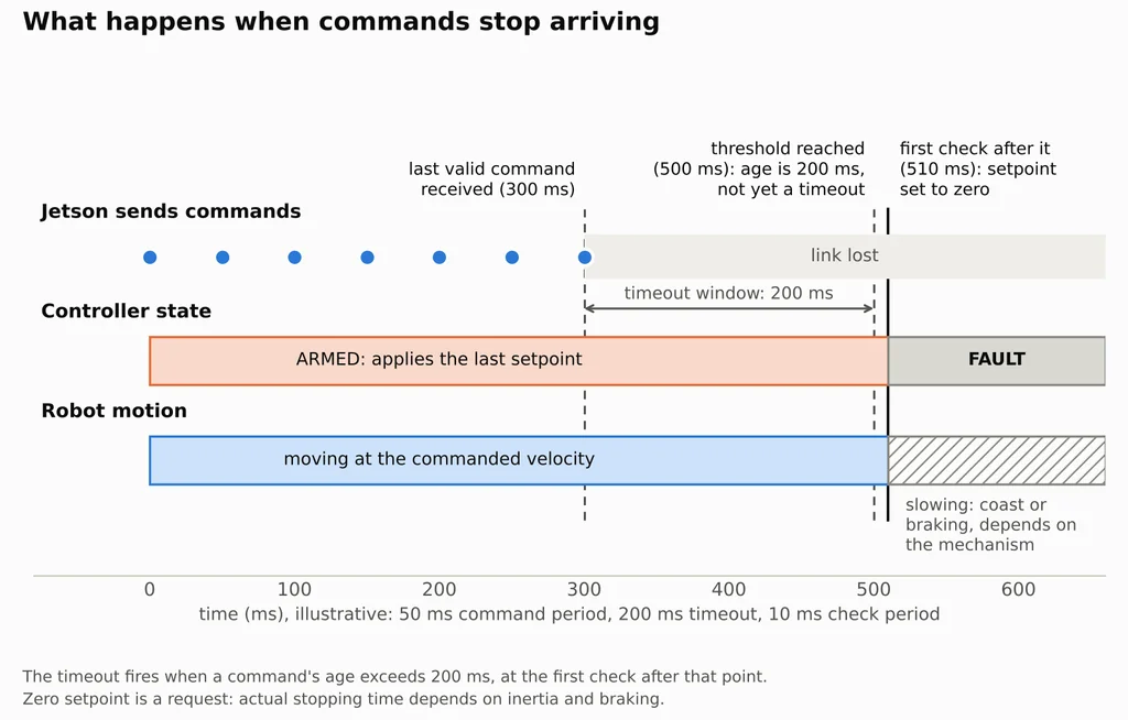
The Jetson sends a command every 50 ms. If one transmission is missed and the next arrives on time, the gap is 100 ms, inside the 200 ms timeout. If commands stop altogether and the MCU checks every 10 ms, it can take up to about 210 ms from the last valid command to detect the loss. At 0.2 m/s, the rover travels about 4.2 cm in that interval. Add the distance the wheels travel while braking or coasting when choosing the timeout.
Bench check. The C state machine passed PC tests for arming, disarming, velocity limits, malformed commands, clock wraparound, and late arrivals. A check at exactly 200 ms left it armed. A check at 201 ms faulted it. The Python sender produced valid frames, the C parser rejected a corrupted frame, and the serial loop ran through a pseudo-terminal.
The PC tests did not exercise an ESP32 timer, UART, or motor driver. Before connecting a motor, stop the sender with Ctrl-C. Measure from the last valid command received and check that the controller faults within the timeout plus the maximum gap between checks. Then inspect the driver output. The setpoint can read zero in a debugger while the PWM pin is still active.
Stopping: timeout, watchdog, driver disable, and power isolation
“Stop” covers four different mechanisms, and they are not interchangeable.
| Mechanism | What it is | What it does not guarantee |
| Zero setpoint (command timeout) | Application logic in firmware that requests zero velocity | It works only if the firmware runs and the loop applies it, and the drive responds |
| Hardware watchdog timer | A timer that resets or panics the chip when software stalls. ESP-IDF describes interrupt, task, and RTC watchdogs; by default its task watchdog only prints a warning unless configured to panic | A reset is not a controlled stop, and it does not catch firmware that runs but misbehaves. Check what your outputs do during and after a reset |
| Driver disable | An enable or safe-torque-off input that inhibits the driver’s outputs according to the driver’s design | Removing torque lets a motor coast, so the load keeps moving until friction or a brake stops it |
| Power isolation | A relay or contactor that opens the motor power path | Stored energy, inertia, and brakes still decide how far the robot travels |
In Figure 1, pressing the emergency stop opens the motor-power contactor even if both processors hang. What happens next depends on the mechanism. A rover may coast after power is removed. A vertical arm may need a brake to hold its load. Choose the stop arrangement for the machine, and test a rover with its wheels lifted before running it on the floor.
When you can skip the extra controller board
Not every system needs a separate microcontroller. Five questions decide it:
- Can anything on the system move hard or fast enough to cause damage or injury? Stationary equipment counts if its actuators can.
- Do you need encoder-based odometry or closed-loop wheel or joint control?
- Must it stop if the main computer crashes or the link drops?
- Does any loop need steadier timing than your Linux software delivers on your hardware (the test below measures this)?
- Does anything need to be in a safe state while Linux is still booting?
If every answer is no, you can often keep everything on the Jetson. Typical cases are a stationary vision box with no hazardous actuator, or a demo with small hobby servos and low consequences. If any answer is yes, the low-level control and failure handling have to live somewhere that survives a Linux failure. That can be a microcontroller board, or a smart actuator or drive that already contains the feedback loop, timeout, and limits. The principle is where that logic lives, not how many boards you buy.
Measure Linux timing on your own Jetson
cyclictest measures how late a thread wakes relative to its scheduled time. Run it once with the Jetson idle, then repeat under load. The commands below use stress-ng for a repeatable comparison. For a robot, repeat the test with the camera and detection pipeline you plan to run. cyclictest manual
sudo apt install rt-tests stress-ng

# Baseline on an idle system, 5 minutes
sudo cyclictest --smp -m -p 80 -i 1000 -D 5m -q

# Under load: start your real workload (camera plus detection), or use a synthetic one
stress-ng --cpu 0 --vm 2 --vm-bytes 512M --timeout 5m &
sudo cyclictest --smp -m -p 80 -i 1000 -D 5m -q
--smp pins one thread per CPU, -m locks memory, and -p 80 sets the real-time priority. The first thread uses a 1,000 µs interval (-i 1000). Successive threads add 500 µs unless you specify -d 0. The test runs for five minutes (-D 5m), and -q prints the summary. Read the Max column for the largest observed wake-up delay on each thread, in microseconds.
Record the kernel version (uname -r), power mode (nvpmodel -q), and workload alongside each result.
What we measured on a Turing Pi 2.5
Configuration: Jetson Orin Nano Super 8 GB in node slot 4 of a Turing Pi 2.5, JetPack 7.2.1 (L4T R39.2.1), kernel 6.8.12-1021-tegra with CONFIG_PREEMPT=y (not PREEMPT_RT), 25W power mode, jetson_clocks not active. Three 5-minute runs per condition of cyclictest --smp -m -p 80 -i 1000 -D 5m -q (6 threads, with intervals from 1,000 to 3,500 microseconds). The load was stress-ng --cpu 0 --vm 2 --vm-bytes 512M.
| Condition | Mean on the thread with the largest delay | Max per run | Largest of three |
| Idle | 6 to 7 µs | 86, 308, 87 µs | 308 µs |
| stress-ng load | 8 to 9 µs | 1,465, 5,311, 5,439 µs | 5,439 µs |
The mean column is each run’s mean wake-up latency on the thread that recorded that run’s largest maximum, shown as the range across the three runs.
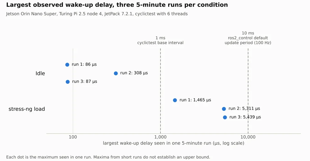
The largest idle delay was 308 µs. Under CPU and memory load, one thread woke 5,439 µs (5.439 ms) late. A delay that long would leave about 4.6 ms of a 10 ms control cycle to read the encoders, calculate a correction, and write it to the drive. We measured thread wake-ups on this Jetson. The test did not run a wheel controller or a camera pipeline.
CPU clocks ranged from 729 to 1,344 MHz at idle and held at 1,344 MHz under load. Swap use stayed at zero in the idle samples and reached 243 MB under load. The test summaries have no timestamps for individual maxima, so we could not tie a particular delay to swap activity. Longer runs or different workloads may produce larger delays.
Troubleshooting
| Symptom | Likely cause | Fix |
| Motors stutter or encoder counts drift when the camera pipeline starts | PWM or encoder sampling is timed in Linux user space and competes for CPU | Use MCU hardware counters for encoder pulses, run the velocity loop in MCU firmware, and send only target velocities from the Jetson |
| The robot keeps moving after the Jetson app crashes or the SSH session drops | The controller has no command timeout, or the only timeout lives on the Jetson | Enforce the timeout on the controller, zero the setpoint on expiry, and require an explicit re-arm |
| The setpoint is zero but the robot keeps rolling | A zero setpoint is a request, and the load coasts or the driver does not brake | Check the driver’s braking and disable behavior, size the timeout to the stopping distance, and keep a hardware stop |
| The robot lurches when the Jetson reconnects | Re-arming restores the last commanded velocity | Zero the velocity on every arm, as the example does, and ramp up deliberately |
A micro-ROS topic does not appear in ros2 topic list | The agent is not running, or the transport settings (serial device, UDP address and port) do not match | Start the agent with the matching transport and check the device path or IP and port on both sides |
| A topic appears but the subscriber receives nothing | Incompatible QoS: a best-effort publisher cannot connect to a reliable subscription | Make the subscription no stricter than the publisher offers |
| Control feels fine, then pauses unpredictably | Scheduling latency spikes in Linux user space | Run cyclictest under load, then move the timed loop to the controller, or evaluate NVIDIA’s RT kernel if one is offered for your release |
| A peripheral you planned on is missing on your board | ESP32 variants differ in peripherals | Check the technical reference manual for your exact chip before choosing a board |
Related Articles
- Distributed ROS 2 on Jetson Orin Nano and Turing Pi 2.5: Raw vs JPEG vs Detections
- NVIDIA Jetson Orin Nano Super on Turing Pi 2.5: Complete Setup Guide
- NVIDIA Jetson on Turing Pi 2.5: Modules, Builds & Use Cases
FAQ
Can a Jetson control motors without a microcontroller?
Yes. It can reach motor drivers through hardware PWM, GPIO, serial, or USB. The real question is whether that is the right architecture for your timing and failure requirements. On a Turing Pi 2.5, remember that only Node 1 has the 40-pin GPIO header.
Does the Jetson have hardware PWM?
Yes. Jetson Linux documents hardware PWM controllers on Orin Nano. Whether a usable output pin exists depends on your carrier and pin configuration. The case for a separate controller rests on encoder handling, scheduled control updates, and independent fault handling, not on PWM alone.
Do all robots need a microcontroller?
No. Stationary systems with no hazardous actuators, simple demos, and robots built on smart actuators that close their own loops can work well without one. The need grows with motion, timing sensitivity, and consequences.
Can PREEMPT_RT replace the microcontroller?
It can reduce scheduling latency, but the kernel documentation gives no worst-case bound, any RT kernel NVIDIA offers for your Jetson release is a separate option (developer-preview quality on R39.2), and it does not give you an independent fault path or a controller that holds a safe state while Linux boots.